Overview
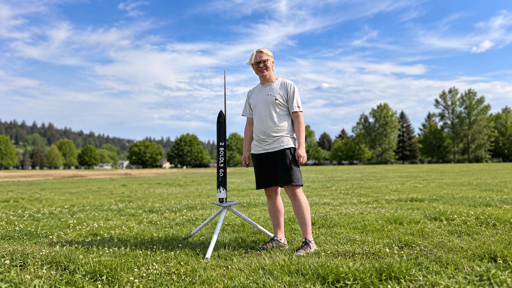
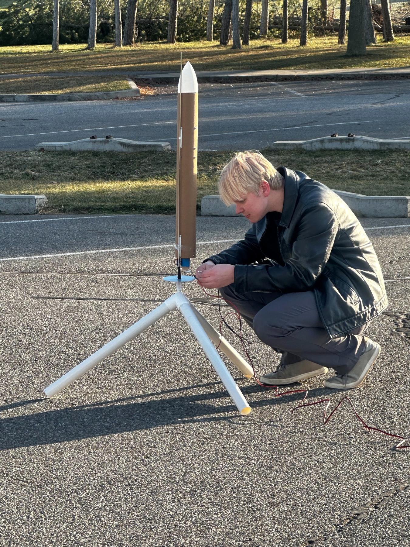
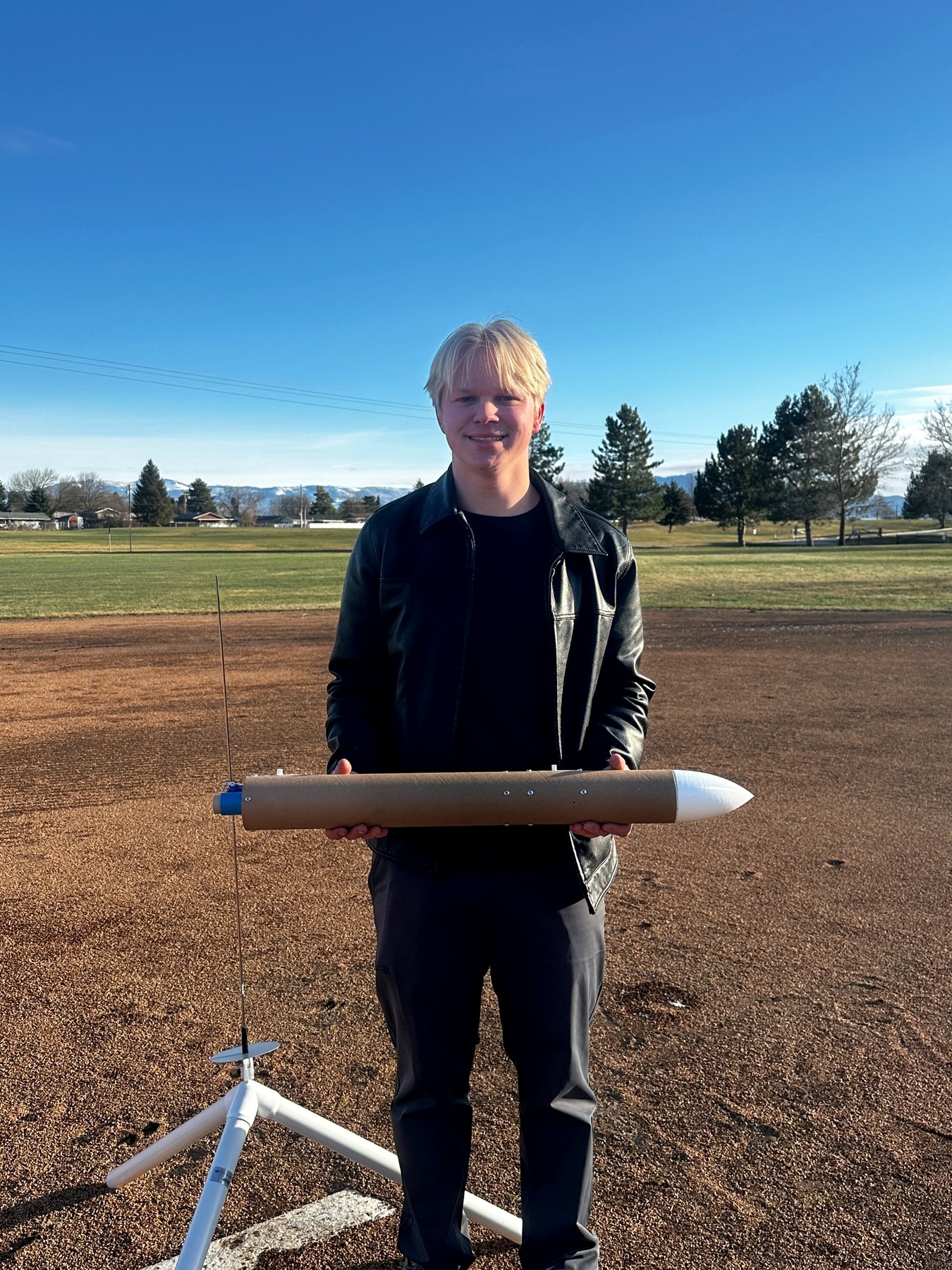
I designed and built a thrust-vector-controlled model rocket around a custom flight computer, flight-control software, and a custom two-axis servo-operated gimbal I 3D printed out of PETG. The onboard system used dual IMUs, an MPU6050 and an LSM6DSOX, a BMP280 altimeter, sensor fusion with Kalman filtering, and closed-loop PID control to estimate the rocket’s motion and actively stabilize it during flight. I also developed a custom Python flight simulation to model the vehicle and tune the control system before launch.
The rocket flew four times, each exposing a new problem to solve and driving the next iteration. This project is very special to me because I watched BPS.Space on YouTube do this many years ago and it is a large reason I am pursuing engineering today. More than any single technical skill, this project taught me persistence: how to test assumptions, diagnose failure, redesign, and keep trying. Most importantly, it taught me not to fear failure and gave me confidence that I am capable of taking on difficult problems and seeing them through.
Development
The project started long before the final thrust-vector-controlled rocket. Before I was comfortable putting a flight computer, active control system, and custom recovery system into a vehicle, I spent time building and flying smaller conventional model rockets to better understand the fundamentals. These early rockets helped me become more comfortable with stability, center of gravity, motor selection, recovery systems, and the practical side of preparing and launching a rocket. They also gave me confidence working with something that I had previously only understood theoretically.
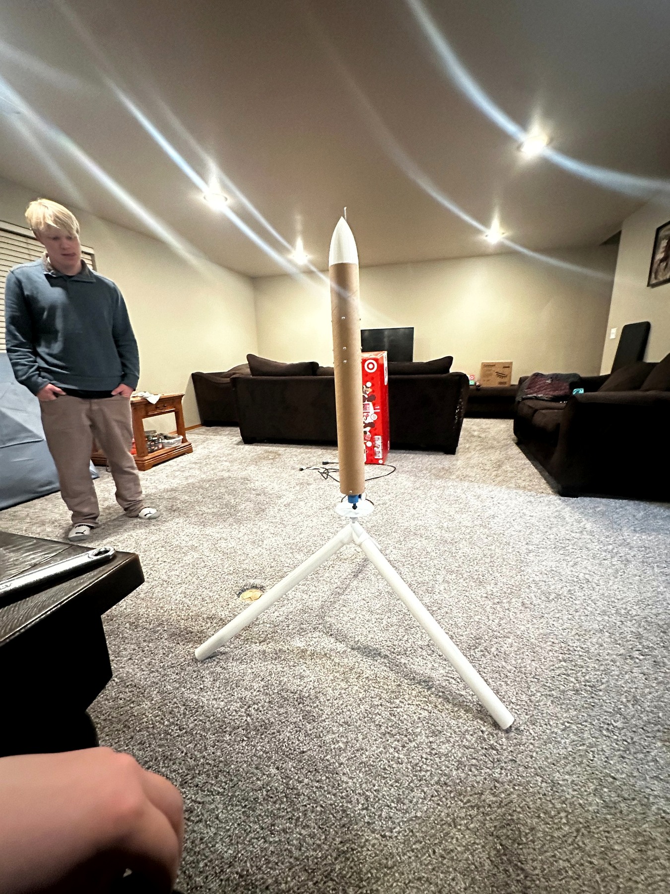
As the project became more complex, I built my own test stand for the thrust-vector-control system. This allowed me to test the gimbal, servos, sensors, and flight software without needing to launch the entire vehicle every time I made a change. I could command different angles, verify that the gimbal moved in the correct direction, test control response, and tune the PID system while the rocket was safely restrained. I also used the stand alongside the Python simulation I developed to better understand how changes to the controller would affect the real vehicle.
The final rocket went through four flight attempts, and almost every one taught me something different.
Flight 1 — Motor Failure
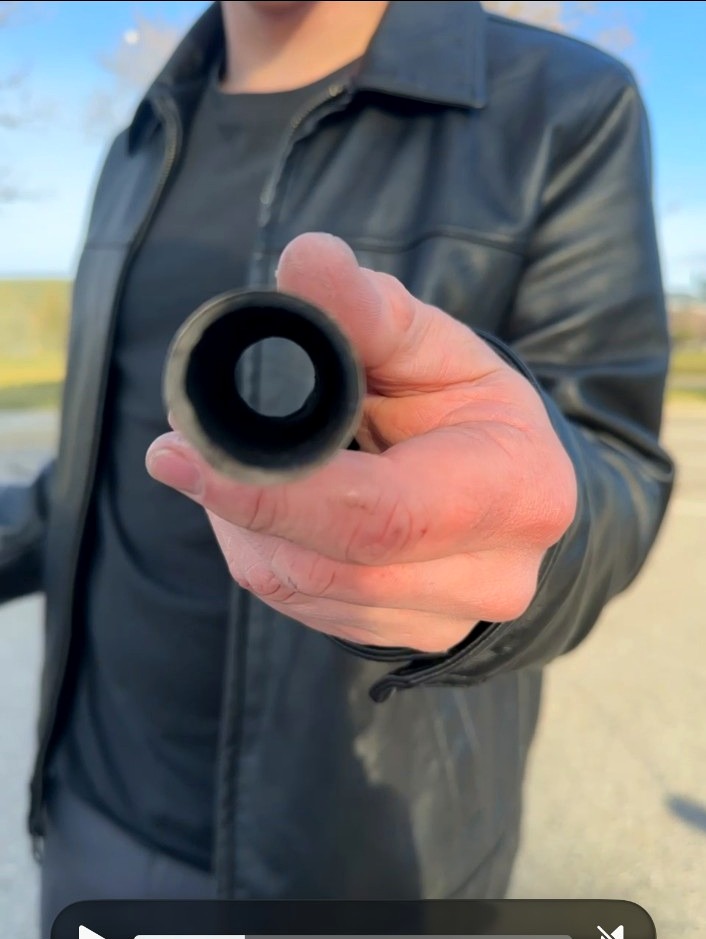
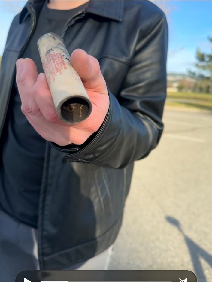
The first flight ended almost immediately when the motor failed shortly after ignition. I had pressure-fit the commercial F15 motor into the rocket, and my best explanation afterward was that the force used to install it had damaged or cracked part of the motor's paper casing. Once the motor came up to pressure, combustion gases were able to escape through the damaged casing instead of remaining contained through the nozzle, resulting in a catastrophic failure.
It was obviously not how I wanted the first attempt to go, but it forced me to think much more carefully about how seemingly small mechanical decisions could affect the entire system. For the next version I changed the motor retention design so that the motor no longer relied on a tight friction fit and instead used a proper mechanical retainer.
Flight 2 — Launch Detection Failure
About a month later I returned with a rebuilt and improved rocket. The motor worked correctly this time, but the vehicle immediately began doing backflips instead of stabilizing itself.
After looking through the flight data, I found that the thrust-vector-control system had never actually entered powered-flight mode. My launch-detection threshold was set too high, and the software was only looking at acceleration along the rocket's Z-axis. Because the rocket left the launch rod at a slight angle, not all of the acceleration appeared along that single axis. The total acceleration was high enough to indicate launch, but the value the software was monitoring never crossed the threshold.
The flight computer therefore never enabled active stabilization. The hardware was working, but the software did not realize that the rocket had launched.
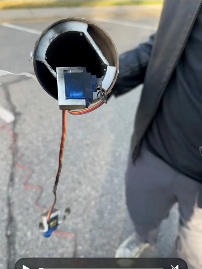
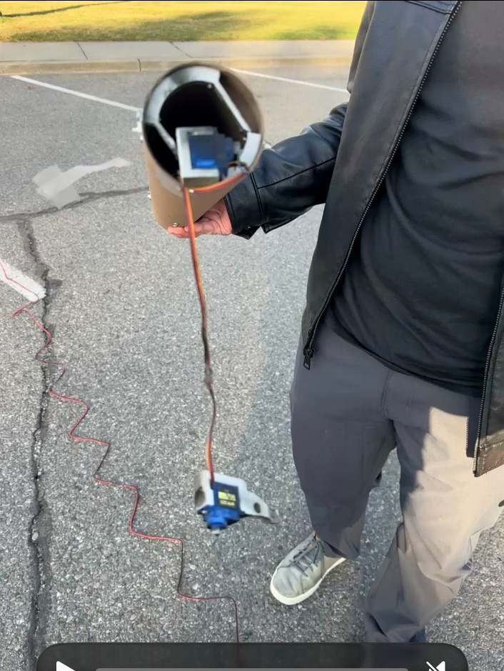
Rather than simply lowering the threshold and hoping it worked, I wanted a way to test the new logic before flying again. I went through frames from the launch video and used them to estimate the rocket's acceleration as it left the rod. I then performed a series of backyard tests where I physically threw the rocket while logging sensor data, trying to reproduce roughly the acceleration and duration it would experience during launch.
The goal was to find a launch threshold that existed in a useful middle ground: low enough that the rocket would reliably detect a real launch, but high enough that normal handling or movement on the launch pad would not accidentally trigger powered-flight mode.
I also rewrote the launch detection to use the magnitude of the three-dimensional acceleration vector rather than relying only on one axis. This meant that launch detection no longer depended as heavily on the exact orientation of the rocket.
Flight 3 — Successful Stabilization
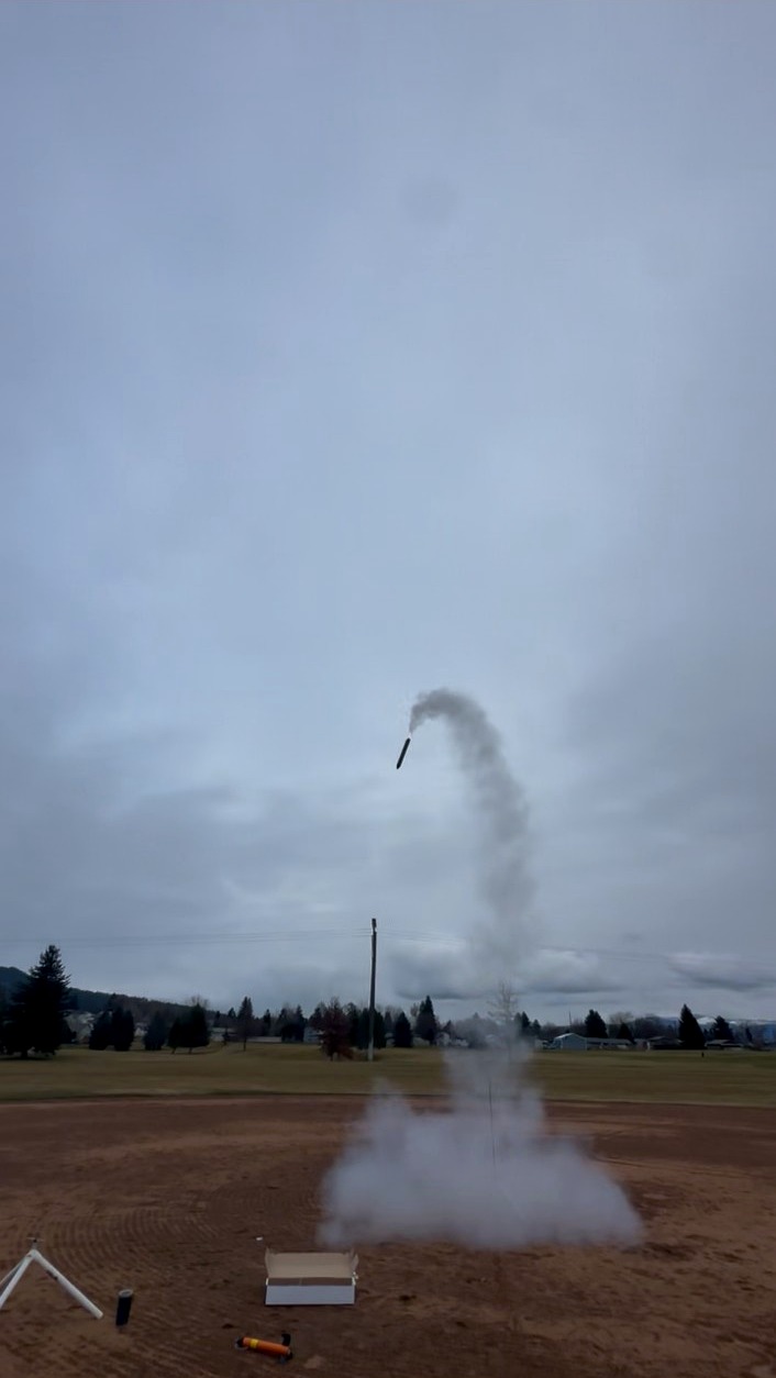
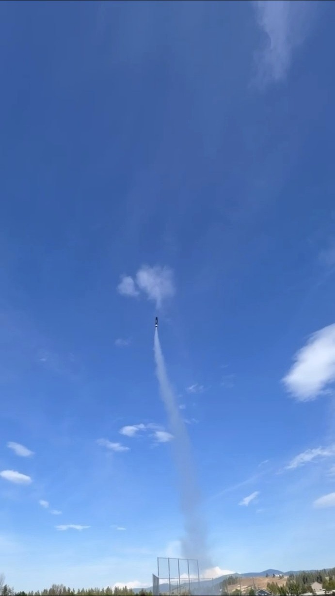
The third launch was the first time the complete thrust-vector-control system operated correctly in flight.
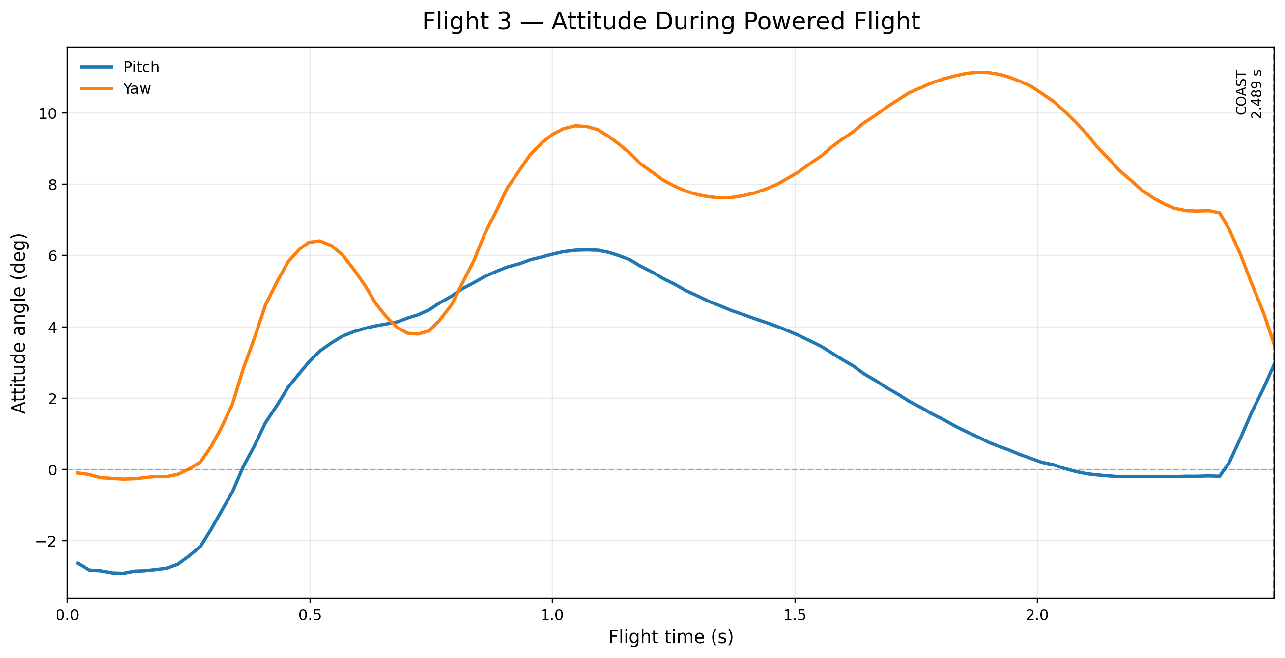
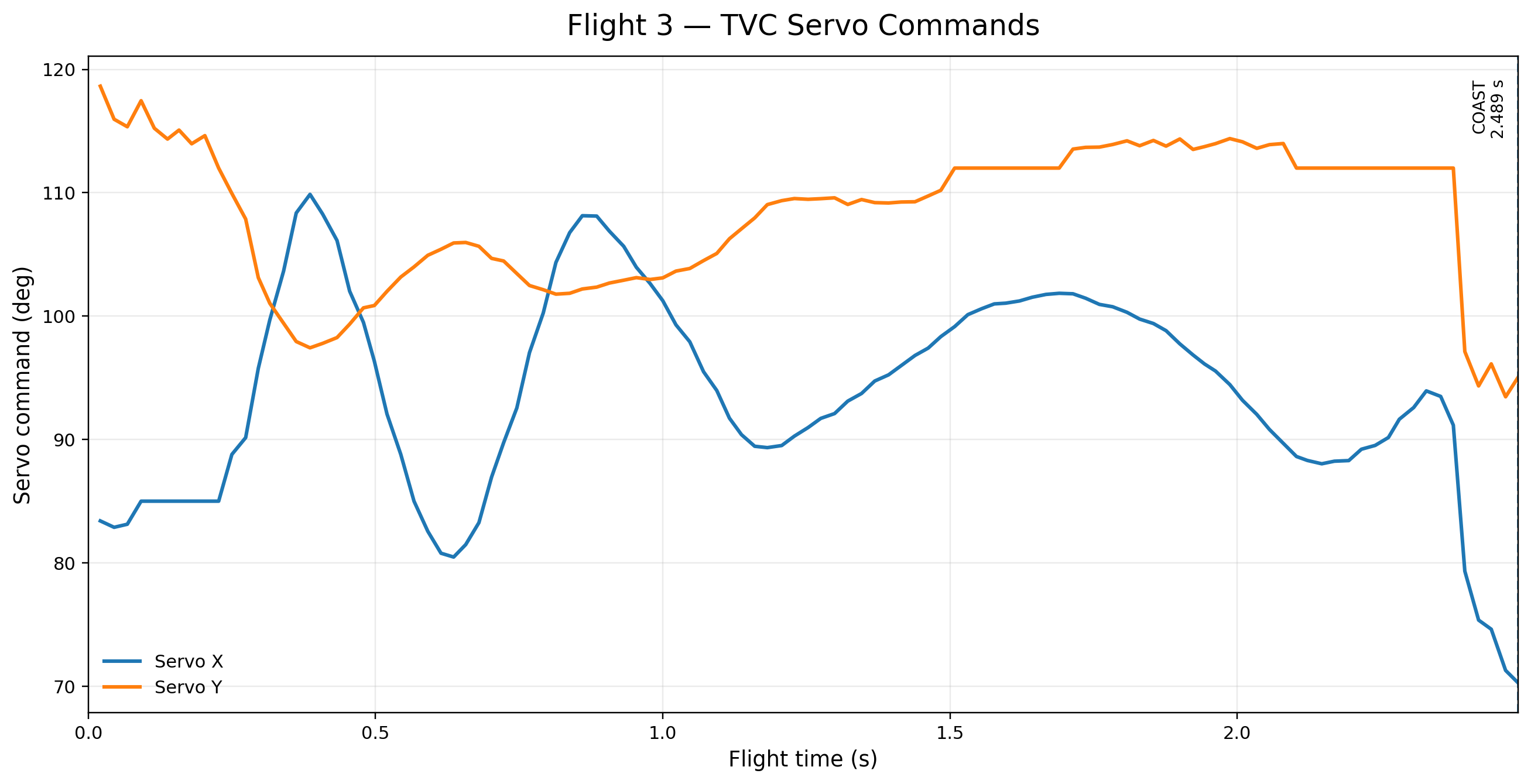
The rocket left the rod and flew almost perfectly straight. The IMUs, Kalman-filtered attitude estimate, PID controller, and servo-driven gimbal all worked together as intended, and the rocket actively corrected its orientation during powered flight.
This was a major milestone for the project because it proved that the core control system actually worked outside of simulation and ground testing.
However, the flight exposed another problem.
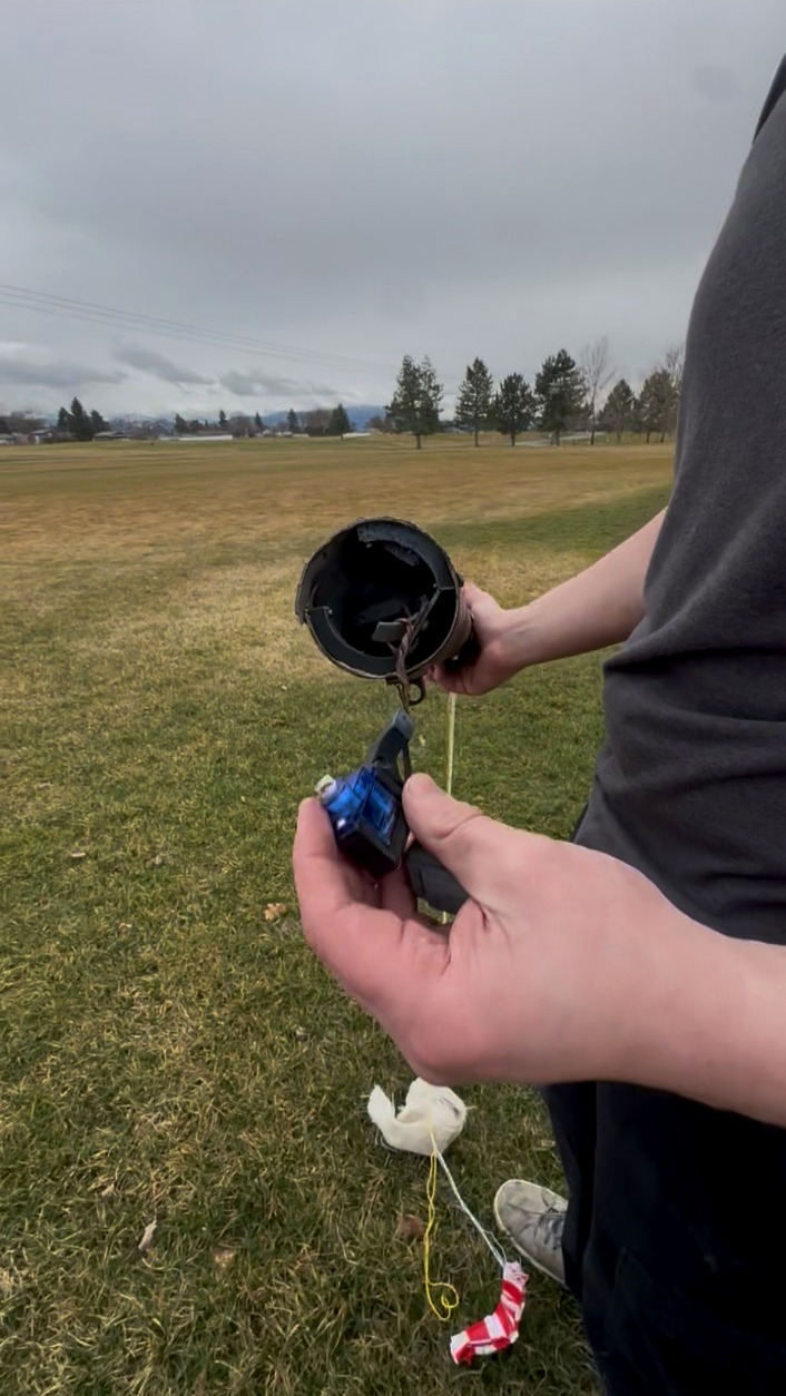
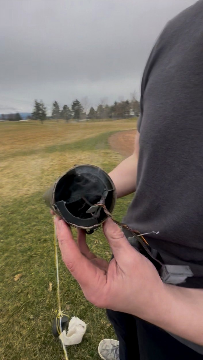
The recovery system was designed to deploy the parachute near apogee, but the rocket did not reach the altitude I had expected. Because the altitude target was set too high, the normal deployment condition was never reached. I had also included an emergency backup timer in the flight software, but during testing I had intentionally set that timer much longer than it should have been and forgot to change it back before launch.
The result was that the rocket returned to the ground before the backup timer expired. The parachute charge eventually fired, but only after the rocket had already impacted.
Once again, the failure was not caused by a single piece of broken hardware. It came from an assumption I had made about the expected flight and a test setting that had accidentally made its way into the flight configuration.
For the next attempt I created an approximate OpenRocket model of the vehicle and used it to get a much better estimate of the expected altitude. I lowered the altitude threshold used by the recovery logic and changed the backup timer to a value that would actually provide meaningful protection if the primary deployment condition failed.
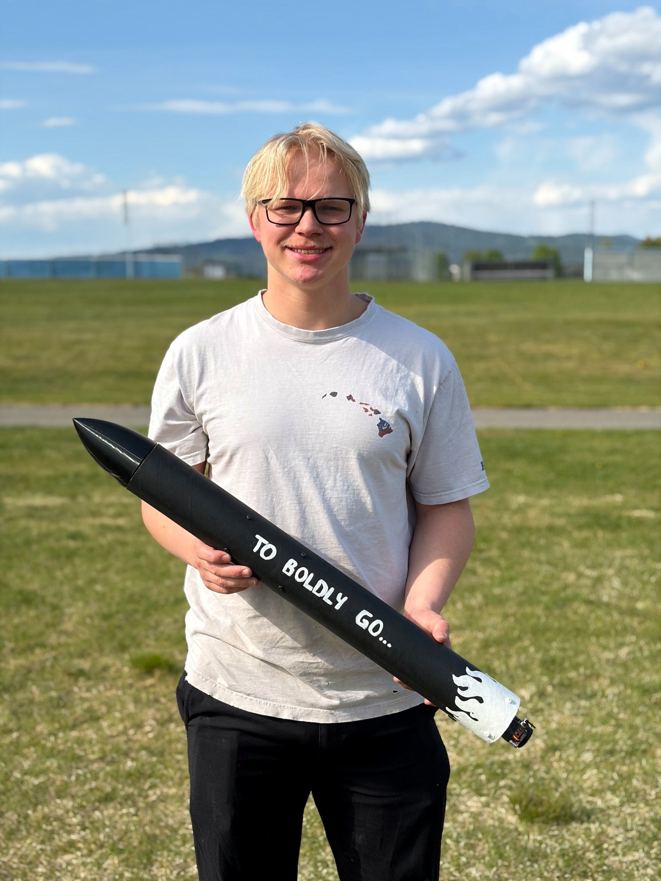
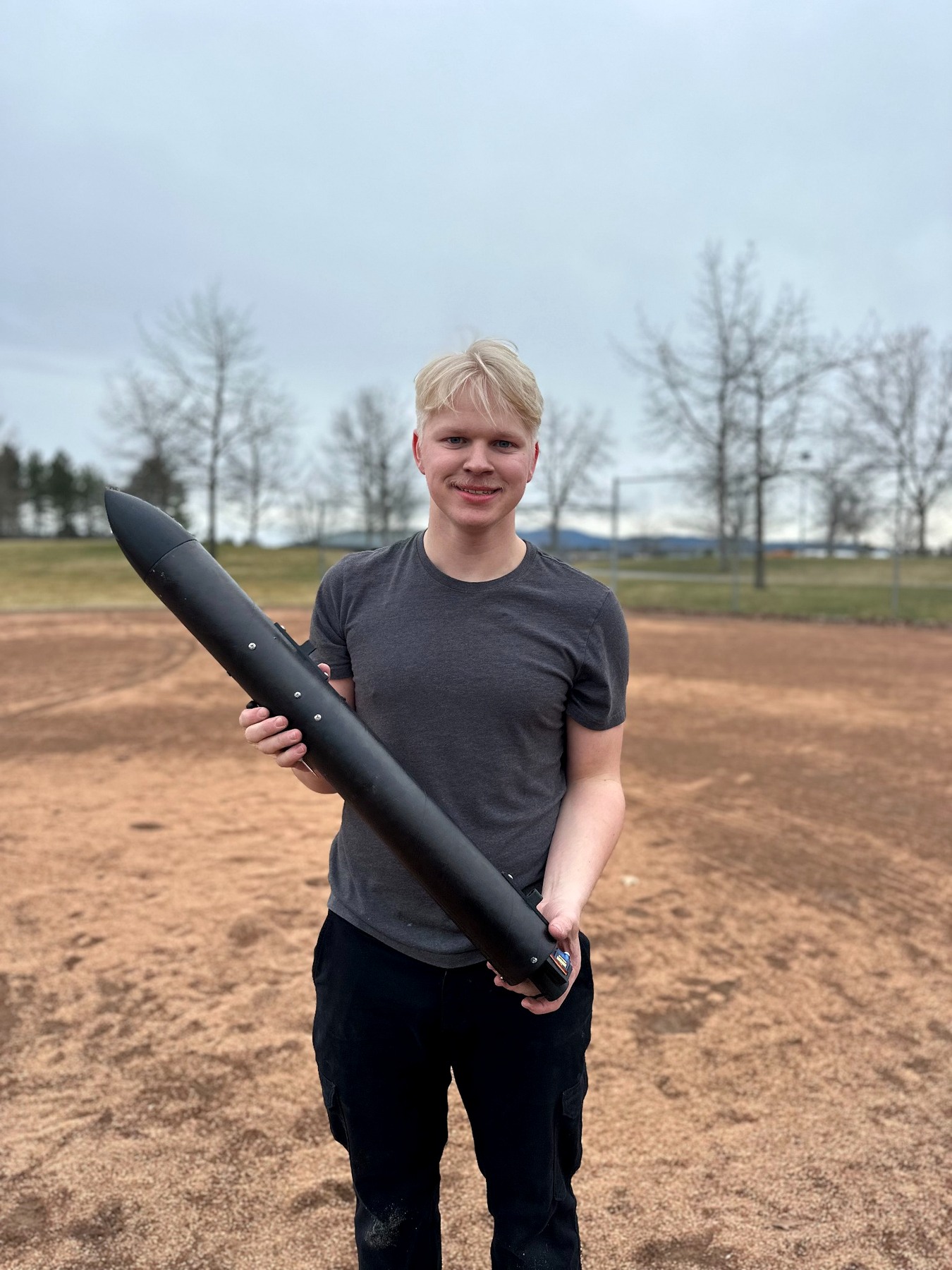
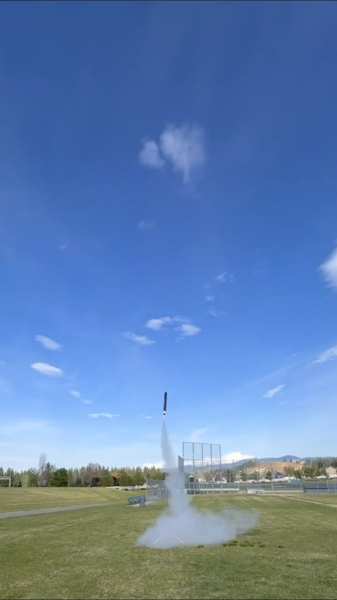
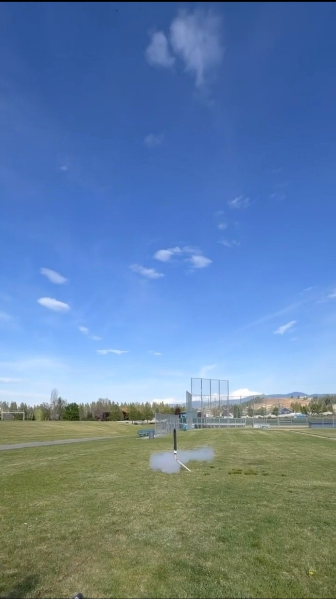
Flight 4 — Final Iteration
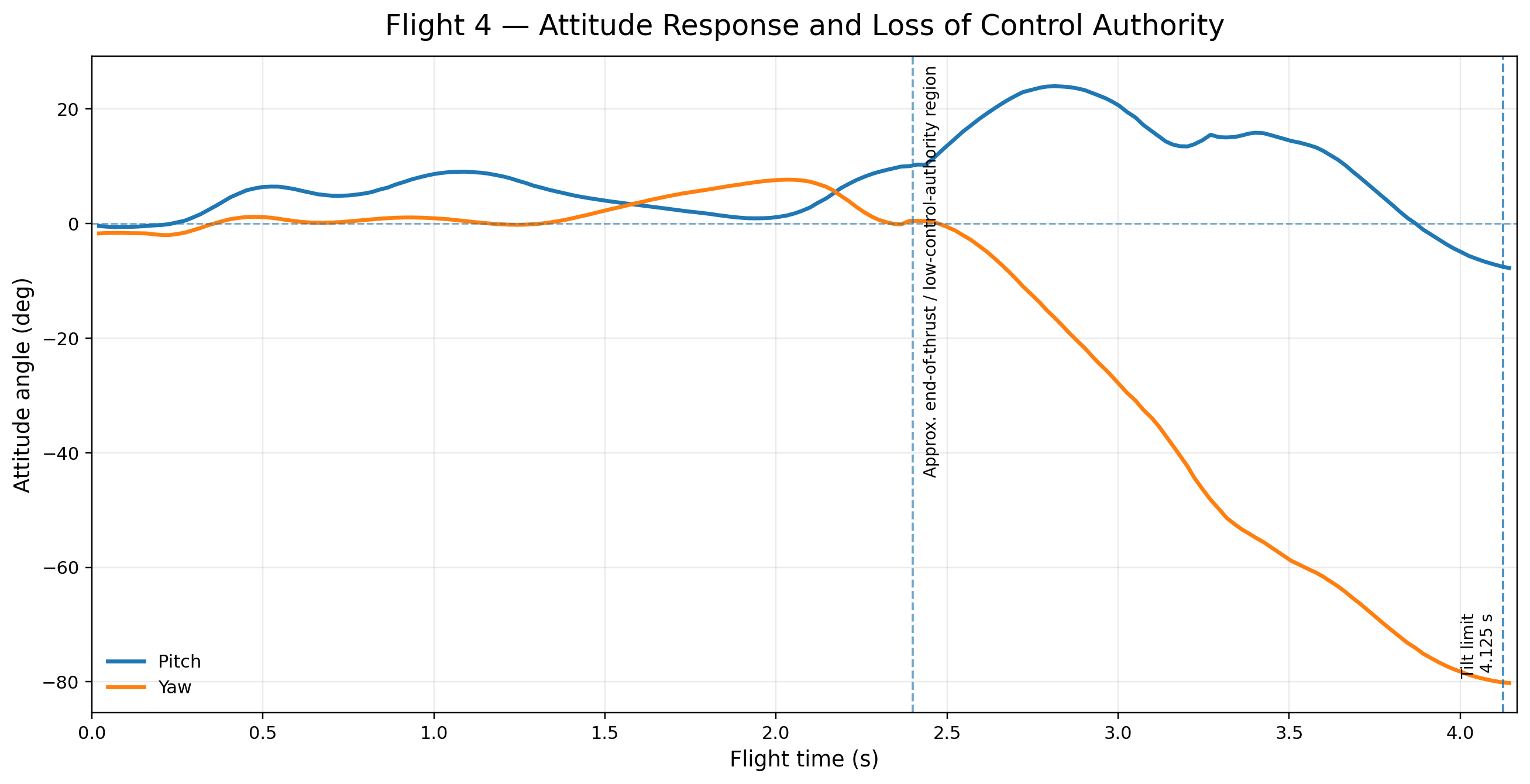
By the fourth flight, almost every major system in the rocket had been changed or validated through one of the previous attempts.
The motor mounting had been redesigned after the first failure. Launch detection had been rewritten around three-dimensional acceleration after the second. The thrust-vector-control system had been proven in flight during the third, and the recovery logic had been updated using more realistic altitude estimates and a properly configured backup timer.
What made the final version work was not one major breakthrough. It was the accumulation of dozens of small lessons from the previous rockets, test-stand runs, simulations, software changes, and failed launches.
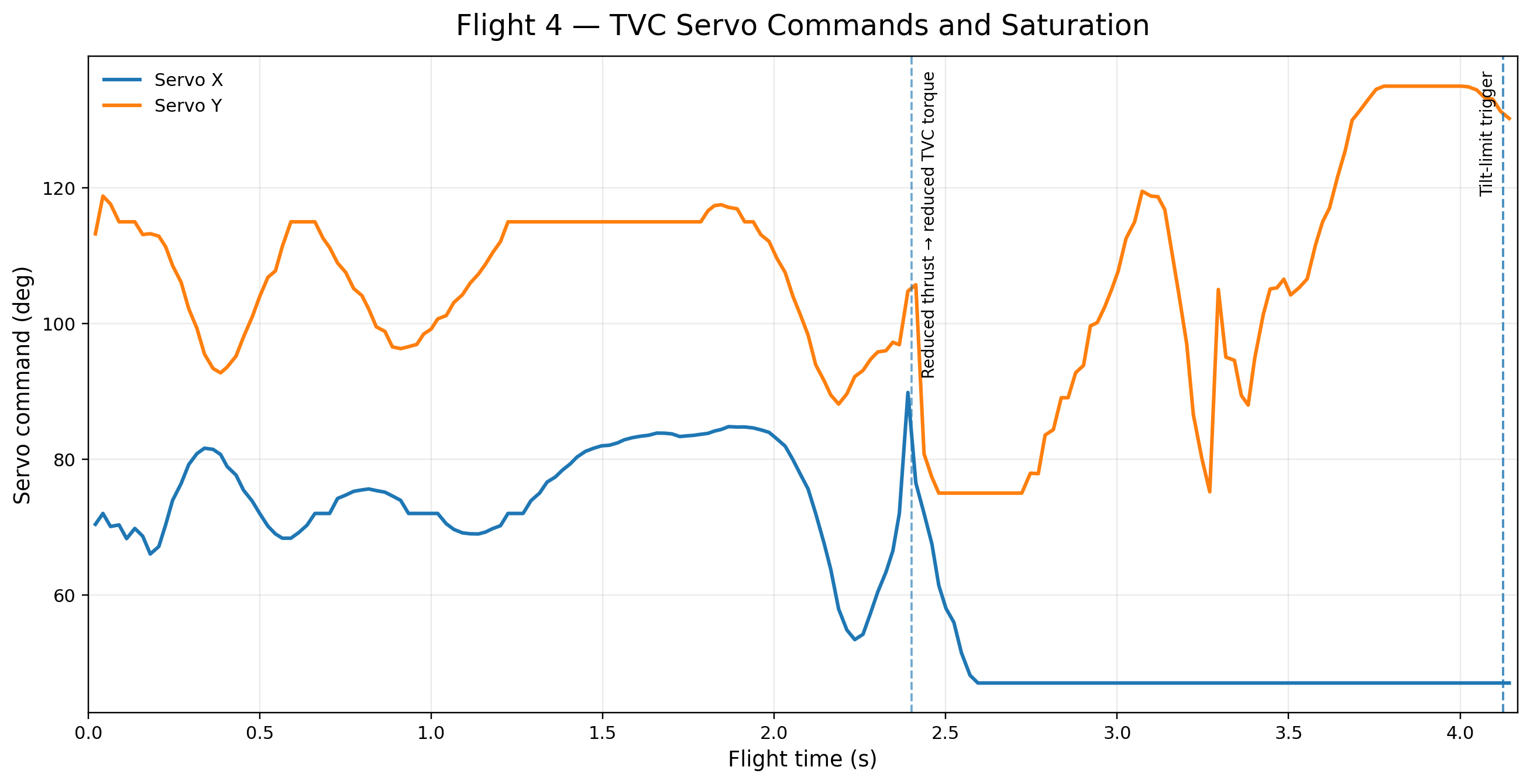
The finished vehicle used an onboard RP2040-based flight computer, an MPU6050 and LSM6DSOX for inertial sensing, a BMP280 for altitude measurements, Kalman filtering for sensor fusion, and closed-loop PID control. The controller commanded two micro servos driving a custom PETG gimbal capable of approximately 12° of movement in each axis. The flight computer also controlled its own electronic pyrotechnic recovery system and contained multiple software failsafes intended to protect the vehicle if the normal flight sequence did not occur as expected.
What the Development Process Taught Me
This was a project I had wanted to accomplish for years. I started thinking about it when I was very young, and there were times I stepped away from it when I was unsure if what I was trying to do would actually work.
The four flights changed the way I looked at failure. Each time something went wrong, there was a reason for it. I could look at the data, video, hardware, or code, come up with an explanation, test that explanation, and make the next version better.
By the end of the project, failure had stopped feeling like the end of an attempt and started feeling like another source of information.
That lesson has stayed with me far beyond this rocket. The project taught me how to break a difficult problem into smaller ones, test my assumptions instead of trusting them, and keep working when the first solution does not work. It also gave me the confidence to take on projects that I may not completely know how to solve when I start them.
Result
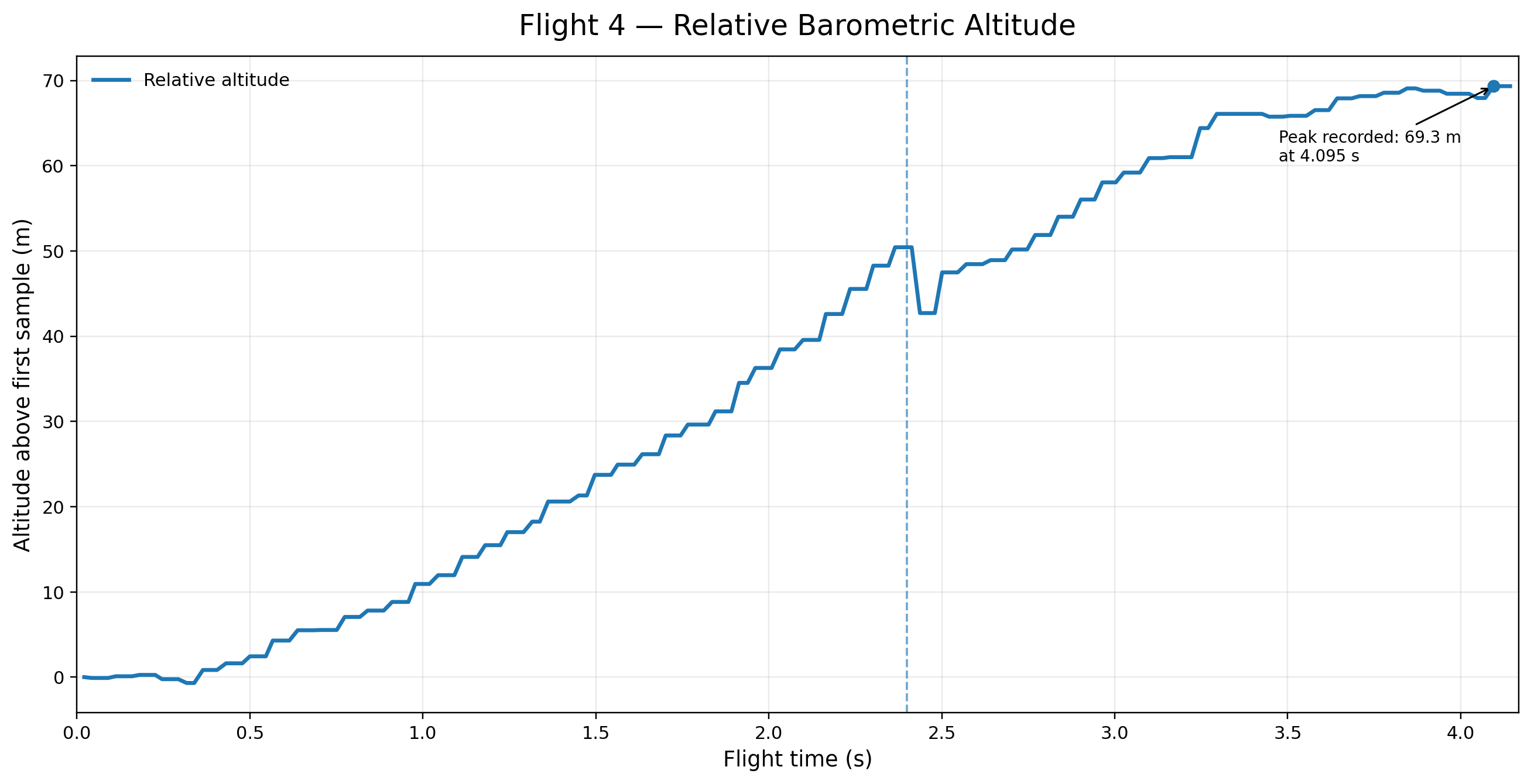
The final flight successfully demonstrated the complete thrust-vector-control system in flight. The onboard flight computer used data from the MPU6050 and LSM6DSOX IMUs, Kalman-filtered attitude estimation, and closed-loop PID control to command the two-axis servo gimbal and actively stabilize the rocket during powered flight. The flight sequence also completed successfully, including apogee detection, electronic parachute deployment, and an undamaged recovery.
After wanting to accomplish this project for years, seeing the complete system finally work was incredibly rewarding. This project was especially meaningful to me because it turned an idea that literally inspired me to go into engineering into something I actually designed, built, tested, and flew successfully.